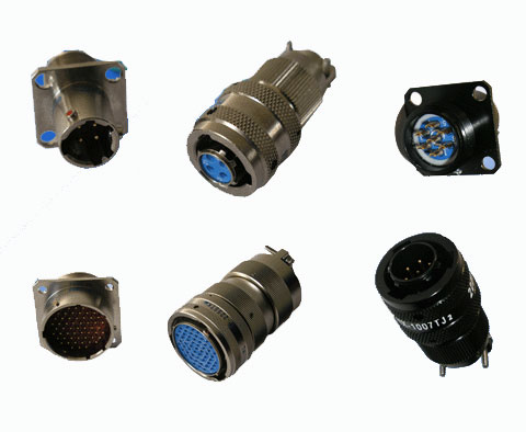
NDT Circular Electric Connector for Nondestructive test equipment
Details:
The Y11 series small circular electric connector is suitable for the strategic and tactic armament system, astronautics satellite system, the aviation navigation transport, the earth launching and receiving system, the high energy high fever industrial system, the communication and test system, the current system of transport and so on the electrical signal connection. This type product has merits such as quick coupling and quick abruption, small volume, and lightweight receptacle with coupling by inlet bayonet locking. The contact is weld. The shell includes shielding and non-shielding type, it also has normal sealed, high vacuum-sealed, high-pressure sealed and rain and dust defending function. The seal type of the receptacle has glue poured and glass fusion, and its mounting styles have flange, nut fixed and wall crossed types and so on.
Conditions of use environment
Relative temperature : -55 ° C ~ +125 C
Relative Humidity : when40 ± 2 ° C, up to 95% ± 95%
Operating Pressure : 101.33kPa ~ 4.39kPa
Sin Vibration: vibration frequency 10Hz ~ 2000HZ, acceleration 196m/s2
random Vibration: Power spectral density of 40m2/s4Hz,the root-mean-square of 239.1m/s2
Impact : acceleration 980.7m/s2
Rain resistance:rainfall 5mm/min
Salt spray:By GJB101A-97 implementation, 3.6.13
The main technical characteristics
Contacts Characteristics
|
Pin-diameter(mm) |
1 |
1.5 |
|
Working current(A) |
5 |
10 |
|
Materials |
Copper Alloy |
Iron alloy |
Copper Alloy |
|
|
Contact resistance(mΩ) |
≤5 |
≤15 |
≤3 |
≤10 |
Insulated resistance
|
Standard air pressure |
Humidity |
Raining |
High temperature conditions |
|
≥3000MΩ |
≥20MΩ |
≥20MΩ |
≥500MΩ |
Voltage resistance
|
Standard air pressure |
AC 1500Vrms |
|
Lower air pressure |
AC 200Vrms |
|
Humid conditions |
AC 500Vrms |
Electric continuity between Shells-- Not more than 0.2Ω
Electric continuity between shielding Shells -- Not more than 0.005Ω
When electromagnetic interference 800MHz, the minimum attenuation is 45dB
Sealing : glue Receptacle 02Mpa
Glass fusion Receptacle Not more than 1×10⁻⁵Pal/s
Mechanical life-span 500
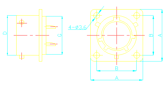
Y11 shape and installation size
Plug a
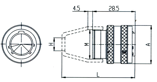
|
Shell NO. |
A |
M |
H |
L |
|
08 |
φ20 .5 |
M14×1 |
φ6 |
41 |
|
10 |
φ23 |
M18×1 |
φ8 |
41 |
|
12 |
φ26 |
M20×1 |
φ10 |
43 |
|
14 |
φ30 |
M24×1 |
φ12 |
49 |
|
16 |
φ33 |
M27×1 |
φ14 |
49 |
|
18 |
φ36 |
M30×1 |
φ17 |
49 |
|
20 |
φ39 |
M33×1.5 |
φ20 |
50.5 |
|
22 |
φ42 |
M36×1.5 |
φ24
|
50.5 |
|
24 |
φ45 |
M39×1.5 |
φ27 |
55 |
Square flange receptacle
|
|
A |
B |
D |
E |
M |
H |
L |
|
08 |
21 |
15±0.15 |
φ13 |
1.5 |
M14×1 |
φ6 |
41.5 |
|
10 |
24 |
18±0.15 |
φ16 |
1.5 |
M18×1 |
φ8 |
41.5 |
|
12 |
27 |
21±0.15 |
φ20 |
1.5 |
M20×1 |
φ10 |
43.5 |
|
14 |
30 |
23±0.15 |
φ23 |
1.5 |
M24×1 |
φ12 |
49.5 |
|
16 |
33 |
25±0.15 |
φ26 |
1.5 |
M27×1 |
φ14 |
49.5 |
|
18 |
36 |
27±0.15 |
φ29 |
1.5 |
M30×1 |
φ17 |
49.5 |
|
20 |
39 |
29±0.15 |
φ32 |
2.2 |
M33×1.5 |
φ20 |
51 |
|
22 |
42 |
32±0.15 |
φ35 |
2.2 |
M36×1.5 |
φ24 |
51 |
|
24 |
45 |
35±0.15 |
φ38 |
2.2 |
M39×1.5 |
φ27 |
55 |
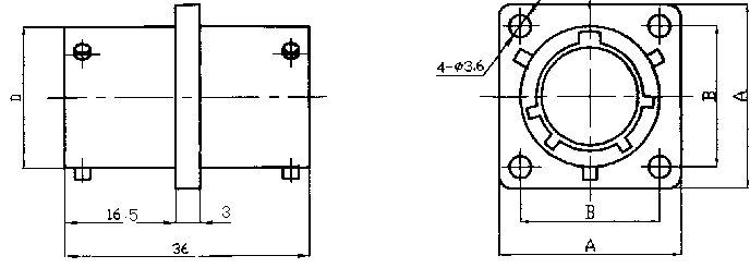
Square flange wall cut through receptacle

|
|
A |
B |
D |
|
08 |
21 |
15±0.15 |
φ13 |
|
10 |
24 |
18±0.15 |
φ16 |
|
12 |
27 |
21±0.15 |
φ20 |
|
14 |
30 |
23±0.15 |
φ23 |
|
16 |
33 |
25±0.15 |
φ26 |
|
18 |
36 |
27±0.15 |
φ29 |
|
20 |
39 |
29±0.15 |
φ32 |
|
22 |
42 |
32±0.15 |
φ35 |
|
24 |
45 |
35±0.15 |
φ38 |
Nut fixed socket receptacle
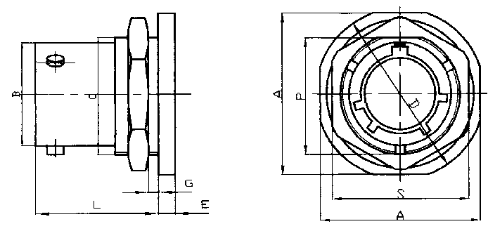
|
|
G |
E |
L |
B |
C |
A |
D |
P |
S |
|
min |
max |
|
08 |
1.6 |
3.2 |
2.5 |
18.5 |
φ13 |
M16×1 |
24 |
φ27 |
15 |
22 |
|
10 |
1.6 |
3.2 |
2.5 |
18.5 |
φ16 |
M20×1 |
27 |
φ30 |
19 |
24 |
|
12 |
1.6 |
3.2 |
2.5 |
18.5 |
φ20 |
M24×1 |
32 |
φ35 |
23 |
27 |
|
14 |
1.6 |
3.2 |
2.5 |
18.5 |
φ23 |
M27×1 |
36 |
φ38 |
26 |
30 |
|
16 |
1.6 |
3.2 |
2.5 |
18.5 |
φ26 |
M30×1 |
38 |
φ42 |
29 |
32 |
|
18 |
1.6 |
3.2 |
2.5 |
18.5 |
φ29 |
M33×1.5 |
41 |
φ45 |
32 |
36 |
|
20 |
1.6 |
6.4 |
3.0 |
22.5 |
φ32 |
M36×1.5 |
46 |
φ49 |
35 |
41 |
|
22 |
1.6 |
6.4 |
3.0 |
22.5 |
φ35 |
M39×1.5 |
50 |
φ53 |
38 |
43 |
|
24 |
1.6 |
6.4 |
3.0 |
22.5 |
φ38 |
M42×1.5 |
53 |
φ56 |
41 |
46 |
Square flange glass fusion receptacle
|
Shell NO. |
A |
B |
D |
G |
|
08 |
21 |
15±0.15 |
φ13 |
φ12 |
|
10 |
24 |
18±0.15 |
φ16 |
φ16 |
|
12 |
27 |
21±0.15 |
φ20 |
φ19 |
|
14 |
30 |
23±0.15 |
φ23 |
φ22 |
|
16 |
33 |
25±0.15 |
φ26 |
φ25 |
|
18 |
36 |
27±0.15 |
φ29 |
φ28 |
|
20 |
39 |
29±0.15 |
φ32 |
φ31 |
|
22 |
42 |
32±0.15 |
φ35 |
φ34 |
|
24 |
45 |
35±0.15 |
φ38 |
φ37 |
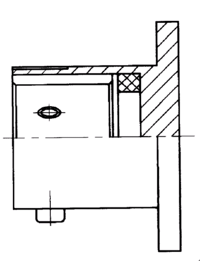
Y11H-0804ZJ11circular flange glass fusion
Accessories
Metal Shield plug cover(Y11-××00-80) Metal Shield receptacle cover(Y11-××00-81)
Empty receptacle(Y11-××00-83)
Open-long cable coat(Y11-××00-85)
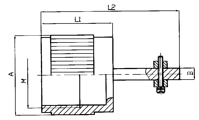
|
Shell NO. |
A |
L1 |
L2 |
B |
M |
|
08 |
φ17 |
15 |
29 |
2.5 |
M14×1 |
|
10 |
φ20 |
15 |
29 |
2.5 |
M18×1 |
|
12 |
φ24.5 |
15 |
31 |
2.5 |
M20×1 |
|
14 |
φ26.5 |
20 |
38 |
3 |
M24×1 |
|
16 |
φ29.5 |
20 |
39 |
3 |
M27×1 |
|
18 |
φ32.5 |
20 |
40 |
4 |
M30×1 |
|
20 |
φ35.5 |
22 |
42 |
4.5 |
M33×1.5 |
|
22 |
φ38.5 |
22 |
42 |
5 |
M36×1.5 |
|
24 |
φ41.5 |
27 |
47 |
5 |
M39×1.5 |
Shielded cables coat(Y11-××00-86)
|
|
L |
H |
φ |
|
08 |
35 |
φ10 |
18 |
|
10 |
35 |
, φ10 |
21 |
|
12 |
37 |
φ14.5 |
25.5 |
|
14 |
40 |
φ16.5 |
29 |
|
16 |
40 |
φ16.5 |
31 |
|
18 |
50 |
φ20 |
34 |
|
20 |
50 |
φ22.5 |
39 |
|
22 |
50 |
φ22.5 |
38.5 |
|
24 |
50 |
φ24 |
41.5 |
Long cable coat(Y11-××00-88)
|
|
A |
B |
E |
D |
M |
L1 |
L2 |
|
08 |
φ14 |
φ6 |
φ13 |
φ17 |
M14×1 |
29 |
35 |
|
10 |
φ17 |
φ8 |
φ16 |
φ20 |
M18×1 |
29 |
35 |
|
12 |
φ20 |
φ10 |
φ19 |
φ26.5 |
M20×1 |
30 |
37 |
|
14 |
φ24 |
φ12 |
φ23 |
φ22.5 |
M24×1 |
34 |
43 |
|
16 |
φ26 |
φ14 |
φ25 |
φ29.5 |
M27×1 |
34 |
43 |
|
18 |
φ30 |
φ17 |
φ29 |
φ32.5 |
M30×1 |
34 |
43 |
|
20 |
φ33 |
φ20 |
φ31 |
φ35.5 |
M33×1.5 |
36 |
45 |
|
22 |
φ36 |
φ24 |
φ34 |
φ38.5 |
M36×1.5 |
36 |
45 |
|
24 |
φ39 |
φ27 |
φ37 |
φ41.5 |
M39×1.5 |
41 |
50 |
Heat shrink type 1 cable coat(Y11-××00-84)
|
|
φA |
φB |
φC |
φD |
M |
L1 |
L2 |
|
08 |
20 |
9 |
11 |
13 |
M14×1 |
27 |
15 |
|
10 |
24 |
10 |
12 |
14 |
M18×1 |
27 |
15 |
|
12 |
26.5 |
13 |
15 |
17 |
M20×1 |
30 |
15 |
|
14 |
30.5 |
17 |
19 |
21 |
M24×1 |
31 |
16 |
|
16 |
33 |
18 |
20 |
22 |
M27×1 |
31 |
18 |
|
18 |
36 |
23 |
25 |
27 |
M30×1 |
34 |
22 |
|
20 |
39.8 |
24 |
26 |
28 |
M33×1.5 |
35 |
20 |
|
22 |
42 |
27 |
29 |
31 |
M36×1.5 |
34 |
22 |
|
24 |
45 |
30 |
32 |
34 |
M39×1.5 |
36 |
24 |
Heat shrink type 2 cable coat(Y11-××00-89)
|
|
φA |
φB |
φC |
φD |
M |
L1 |
L2 |
|
08 |
20 |
8.7 |
12.8 |
14.8 |
M14×1 |
33 |
20 |
|
10 |
24 |
10 |
14.4 |
16.4 |
M18×1 |
33 |
20 |
|
12 |
26.5 |
15 |
19.1 |
21.1 |
M20×1 |
33 |
20 |
|
14 |
30.5 |
18.2 |
22.3 |
24.3 |
M24×1 |
33 |
20 |
|
16 |
33 |
18.2 |
22.3 |
25.3 |
M27×1 |
33 |
20 |
|
18 |
36 |
24.5 |
28.7 |
30.7 |
M30×1 |
33 |
20 |
|
20 |
39.8 |
24.5 |
28.7 |
30.7 |
M33×1.5 |
35 |
20 |
|
22 |
42 |
27.7 |
31.8 |
33.8 |
M36×1.5 |
35 |
20 |
|
24 |
45 |
30 |
31.8 |
34 |
M39×1.5 |
35 |
20 |
Y11 insulation installation location transform plate
|
Marker code |
Ⅰ |
Ⅱ |
Ⅲ |
Ⅳ |
Ⅴ |
|
Keyway installation of five letters |
I |
L |
T |
V |
Y |
|
And the main point of the Key |
0° |
100° |
150° |
155° |
95° |
Y11 Contacts Kong-listed
Note : This map -- the connector inserted a pin-View。
Implementation of the standards
Q/321283LSB03-2004
Model signs Y 11 X Ⅱ - 20 41 Z J 10 - 2
|
Code |
Y |
11 |
X |
Ⅱ |
- |
20 |
41 |
Z |
J |
10 |
- |
2 |
|
No |
① |
② |
③ |
④ |
|
⑤ |
⑥ |
⑦ |
⑧ |
⑨ |
|
⑩ |
①Circular Connector
② design NO.
③ categories : X-rubber seal, H- glass fusion (receptacle), P- shielding glue seal, S-copper shell glue seal
④ dislocation NO. : I, II, III, IV, V, No. 1 no Tagging
⑤ Shell NO. : 08,10,12,14,1, 6,18,20,22,24
⑥Q’ty of conta, , , , , , ct : 4,7,10,1, 2,16,19,21,26,32,41,55,61
⑦ Connector categories : T-Plug, Z- re, , ceptacle
⑧ Contacts type : J-pin, K-jack
⑨ mounting styles : 10-square flange, 11-round flange, 14-nut fixed
⑩ cable coat forms : 2-jiaxianban, 5- heat shrink type 1,
5a- heat shrink type 2, 6-shielding